There are many factors that contribute to the performance of a pneumatic system. Some of these factors are: quantity and type of fittings
leading to the cylinder, tube length and capacity, cylinder operating load, and air pressure.
The following chart allows a look-up of the resulting cylinder speed in seconds for a given valve Cv and cylinder diameter.
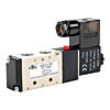
The sizing table below relates various AutomationDirect air valves to cylinder bore sizes between 7⁄16" and
4". The cylinder operating speed resulting from the use of each valve/cylinder combination are shown in the chart:
| Theoretical time (in seconds) required to make a inch stroke |
| Valve Series |
Cv |
Cylinder Bore Sizes (in inches) |
| 7/16 |
9/16 |
3/4 |
7/8 |
1 1/16 |
1 1/4 |
1 1/2 |
2 |
2.5 |
3 |
3 1/4 |
4 |
| BVS series |
0.02 |
|
|
|
|
|
|
|
|
|
|
|
|
| 0.05* |
|
|
|
|
|
|
|
|
|
|
|
|
| AVP series |
0.051 |
|
|
|
|
|
|
|
|
|
|
|
|
| AVS series |
0.67 |
|
|
|
|
|
|
|
|
|
|
|
|
| 0.78 |
|
|
|
|
|
|
|
|
|
|
|
|
| 0.89 |
|
|
|
|
|
|
|
|
|
|
|
|
| 1.0 |
|
|
|
|
|
|
|
|
|
|
|
|
| 1.39-1.40 |
|
|
|
|
|
|
|
|
|
|
|
|
| 1.67-1.68 |
|
|
|
|
|
|
|
|
|
|
|
|
| CMV series |
0.1 |
|
|
|
|
|
|
|
|
|
|
|
|
| 0.2 |
|
|
|
|
|
|
|
|
|
|
|
|
| 0.5 |
|
|
|
|
|
|
|
|
|
|
|
|
| 0.65 |
|
|
|
|
|
|
|
|
|
|
|
|
| 1.0 |
|
|
|
|
|
|
|
|
|
|
|
|
| 1.2 |
|
|
|
|
|
|
|
|
|
|
|
|
| CVR series |
0.89 |
|
|
|
|
|
|
|
|
|
|
|
|
| 5.29 |
|
|
|
|
|
|
|
|
|
|
|
|
NA = Not Available. BVS valves with Cv of 0.05 can only operate at or below 30PSI; some other BVS valves are only rated for 90PSI (please double-check the actual ratings if using high inlet pressures)
NS = Not Suitable. Valve/cylinder combinations that result in low theoretical speeds will likely result in jerky or lurching motion.
VF = Very Fast. Predicting theoretical speeds is not practical beyond certain limits (see note below). Other "fast" speeds that ARE shown should be taken with a grain of salt (see note below).
¹ The pressure drop shown is the DROP ACROSS THE VALVE ONLY, see note below. In practice, you can not choose ΔP (pressure drop) - the pressure drop of a given system is dependent on many things.
NOTE: This chart does not take into account tubing diameter or length, number or size of fittings and orifices, size or weight of the load, etc. You may need to factor in these (and other) values to determine the actual duration of a stroke.
There are also practical limits to how fast a cylinder can physically operate.
The first general rule of thumb is choose a cylinder which will allow for at least 25% more force than
what is required. For extremely fast operations, choose a cylinder which will allow for 50% more force
than what is required. This will leave 25% or 50% of inlet pressure to satisfy system losses.
The second rule of thumb is to select a directional control valve which has the same port size as the
cylinder which it will be operating. For large valves, internal flow capacity is typically the same or greater than the capacity of the intended connection
fittings. On smaller valves, the internal flow capacity is typically much less than that of the connection fittings. But always be sure to check the valves flow rate, and do not rely solely on the port size.
Lastly: use large diameter tubing (relative to cylinder bore), keep the tubing length as short as possible and use as few fittings as possible.
If a specific cylinder speed is desired, it's advisable to size the valve, tubing, fittings, and cylinder for a faster stroke. And then use flow control valves to slow the cylinder down to the desired speed. If extremely fast action is desired, some trial and error testing will probably be required. Consider the use of cushioned cylinders to prolong the life of the components in high speed systems.

 Loading...
 Cookies are not enabled on your browser.